Versatile Switch Box
SORRY! NO LONGER
AVAILABLE
Until now, to operate your dolls' house lights you had two
choices: heave the house forward, reach round the back and operate
slide switches in a "pot luck" fashion or buy and fit an elegant (but
expensive) remote control system with battery-powered handset.
Now there is an alternative: SatCure supply a simple, low cost kit
from which you can build a switching box to control your lights. The
kit includes a plastic box, six miniature toggle switches, six Light
Emitting diodes, resistors and an umbilical cord to connect it to the
lighting circuit.
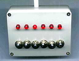 The
end result is a small box measuring just 76 x 57 x 25mm (3" x 2.25" x
1") with six switches and LEDs that light when a switch is "on". The
umbilical cord is an unobtrusive white cable 5mm thick and 1 metre
long. The combination can easily be hidden away when not in use or
screwed firmly to a surface.
The
end result is a small box measuring just 76 x 57 x 25mm (3" x 2.25" x
1") with six switches and LEDs that light when a switch is "on". The
umbilical cord is an unobtrusive white cable 5mm thick and 1 metre
long. The combination can easily be hidden away when not in use or
screwed firmly to a surface.
Tools
You will need a soldering iron, fine-tip pliers, wire cutters, a
drill and a size #1 "Pozidriv" screwdriver. An 8mm spanner makes it
easy to tighten the nuts on the toggle switches, but you can use
pliers if necessary.
Suitable drill bits and solder are supplied.
Construction
Construction is quite straightforward. The switches and LEDs can
be mounted in the lid of the box to allow easy access for soldering.
Scribe two parallel lines on the underside of the lid and mark these
off at 10mm intervals. Drill the two rows of holes.
Now fit a nut to each toggle switch, push the switch into
the hole and fit the star washer and nut to the thread to secure it.
Push the LEDs into their holes, leaving the paper tape carrier in
place. Put folds in the paper tape so that the LEDs sit straight.
Apply a suitable adhesive over the LEDs on the underside of the lid
and leave this to dry.
Now you can remove the paper tape and bend the LED wires ready for
soldering. The wires from the flat sides of the LEDs must be
connected together by soldering a separate piece of wire across them
all.
Take the resistors and fit one to each of the switch tags nearest
the LEDs. Wrap the resistor wire around the switch tag to secure it
then apply solder. Now solder the other end of each resistor to its
respective unused LED wire and crop off the excess. Finally, connect
the centre tags of the switches together by soldering a wire across
them all.
Cabling
Using a sharp knife, carefully nick the outer sheath of the white
cable approximately 60mm from its end. Bend the cable and work around
it with the knife until the outer sheath can be removed to expose the
8 coloured wires beneath. Wrap the cable-tie around the white cable
sheath about 8mm from its exposed end and pull it tight with pliers.
Snip the long unused cable-tie end off.
 Strip
about 5mm of coloured insulation from each wire and twist the bare
strands. Hook the end of the black wire around the common connecting
wire for the LEDs and solder it in place. Hook the end of the red
wire around the common connecting wire across the switches and solder
it. Now solder each of the remaining coloured wires to a switch where
the resistor is already connected. The order of the wires is
unimportant.
Strip
about 5mm of coloured insulation from each wire and twist the bare
strands. Hook the end of the black wire around the common connecting
wire for the LEDs and solder it in place. Hook the end of the red
wire around the common connecting wire across the switches and solder
it. Now solder each of the remaining coloured wires to a switch where
the resistor is already connected. The order of the wires is
unimportant.
Drill a 6mm hole in the long side of the box and pass the white
cable through from the inside.
Now fit the lid assembly to the box and secure it with the
screws.
Connecting
The free end of the cable should be clipped firmly to the rear of
the dolls' house so that the wires can't be disconnected by a
careless tug. (Adhesive clips are supplied). The black wire must be
connected to the negative terminal of your power supply. (The switch
box will work without this wire but the LEDs will not light).
The red wire must be connected to the positive supply.
Each of the coloured wires can be connected to the appliance or
appliances that you want the respective switch to control.
Limitations and safety
Each switch is capable of handling 2500 milliamps (2.5 Amps).
However, since the red wire is carrying the current for ALL of the
switches, the total current should not exceed 2000 milliamps (2 Amps)
which is the rating of one wire. If your total current exceeds 2
Amps, you must connect an additional "red" wire from the box to the
power supply. You can work out the total current by adding together
the current rating of every lamp or appliance that is likely to be ON
at any one time.
It is a good safety precaution to fit a suitable fuse in-line with
the red wire to prevent the risk of fire, should a short-circuit
occur. The fuse should be rated at T2.0A so that it will melt before
the wire does!
You can modify the switch box wiring to suit your own purposes.
For example, if you prefer to have five individual light switches and
one master switch to cut the power to all of them, you can simply
connect the red wire through the end switch instead of to the common
connecting wire. The end switch now acts as a master switch.
Alternatively, you can fit a seventh switch as the master and connect
the red wire through this, leaving all six switches available as
before.
The switches are actually "changeover switches". You'll notice
that each switch has a "spare" contact. This contact is "on" when the
other is "off". So if you have an application where one appliance is
always on when another is off, you can connect both appliances to one
switch. (If you still want six switches to operate, you will need to
add an additional wire of course since one switch now uses two of the
available wires.)
Switch Box Kit £19.95
Copyright ©1999 Martin Pickering
Version 1.1 updated on 3/5/99
This file may be downloaded for private and personal use but NO part
of it may be published in any form without the prior permission of
the author.